WebGL LOD implementation
June 9 2015 4:56 PM
This article explains how to implement a simple level of detail (LOD) which can be used as a module for easily rendering large dynamic or static shapes. This implementation currently work with WebGL and the Three.js library but can effortlessly be adapted.
In my previous blog post, I was speaking about a way to increase performance when rendering a large terrain or water. This way was a grid in screen space projected in the world space. Even if it is a cool idea, there are some flaws with it. Indeed, vertices slides in the 3D plane, generating weird effects. I mentioned very quickly (too quickly in fact) the concept of level of detail. Further this article, I had several conversations with “LOD lovers”.
This is in order to really compare both methods I made a simple LOD implementation in WebGL. The aim is to have a modular implementation which can be reused with as few as possible CPU instructions.
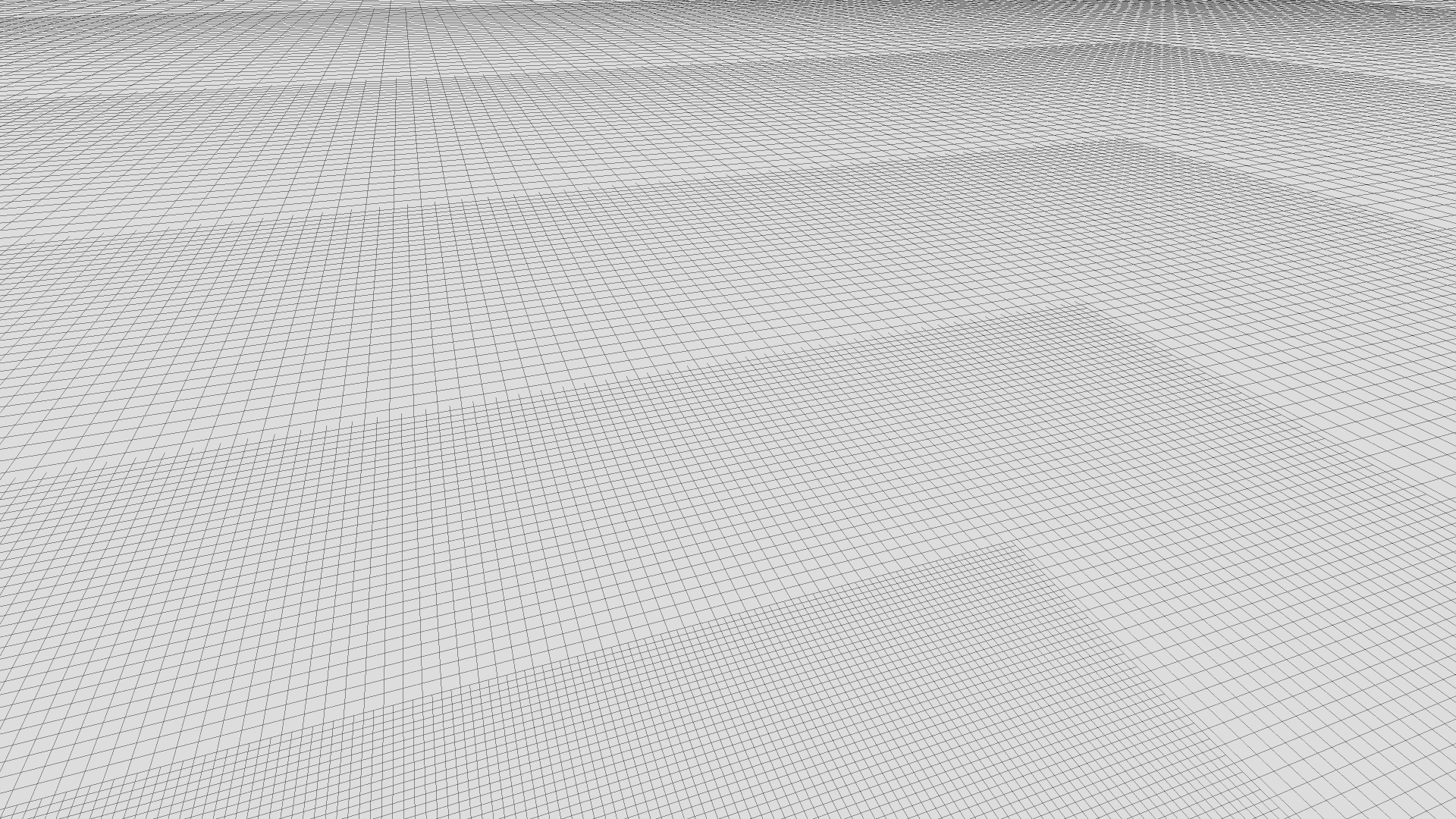
Projected grid VS LOD live demo
Level of detail
The aim of level of detail is to decrease the complexity of a 3D object. When an object in a scene is far enough from the camera, we can reduce texture resolution or the number of triangles.
Here, we focus on the complexity reduction of a grid, for rendering, as example, large terrain or water surface.
This simple implementation will not take into account the shape with a quad-tree reduction, frustum culling or other things. It will only reduce complexity of a grid, on which we can apply a displacement map.
Explanation
In order to explain the concept of this implementation, we will dissociate what’s happening on a frame and what is going on the camera displacement.
Let’s analyze the basics
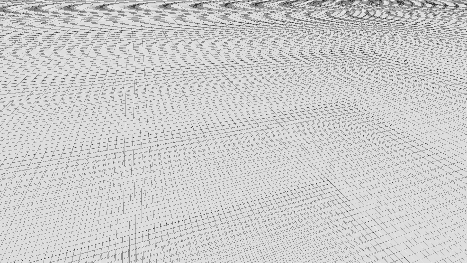
When rendering a frame, the camera is at a given position P. The first step is to project the camera position on the surface we want to render, P’. Around this projection P’, we want to draw grids with different size, but same resolution. That way, it is conceivable to increase the efficiency of rendering with a small loss of quality.
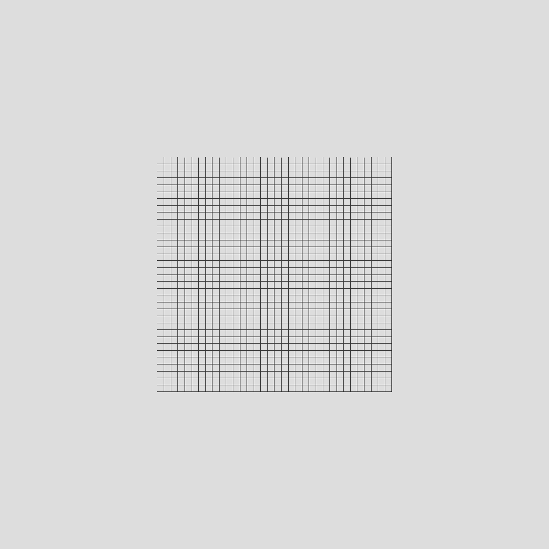
Concretely, we generate a grid with a resolution named K. This grid has K*K squares. The idea is to repeat this grid with different sizes. The initial size of the grid is here named S. We will now add a second level of detail. This level is the grid with a size of S*2. That way, we can add a given number of levels of detail up to N levels.
In summary, we have 3 parameters:
- the grid resolution K
- the size of the first level S
- the number of levels N
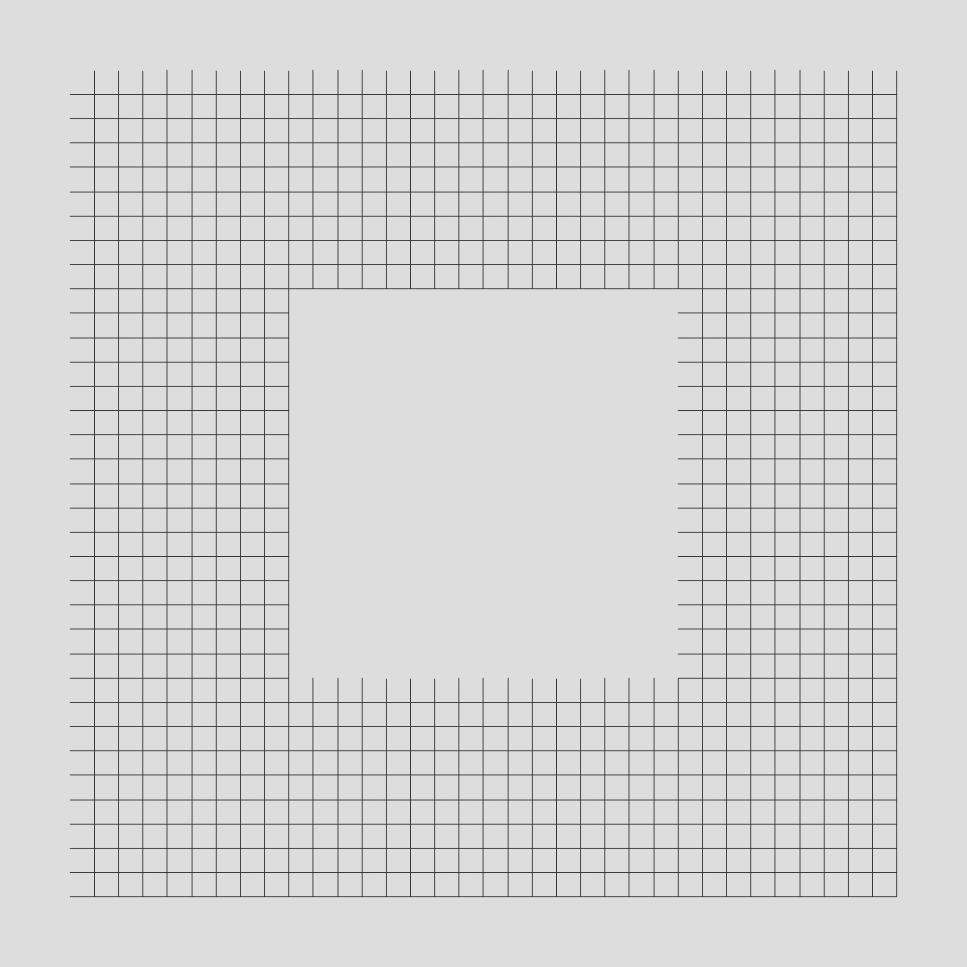
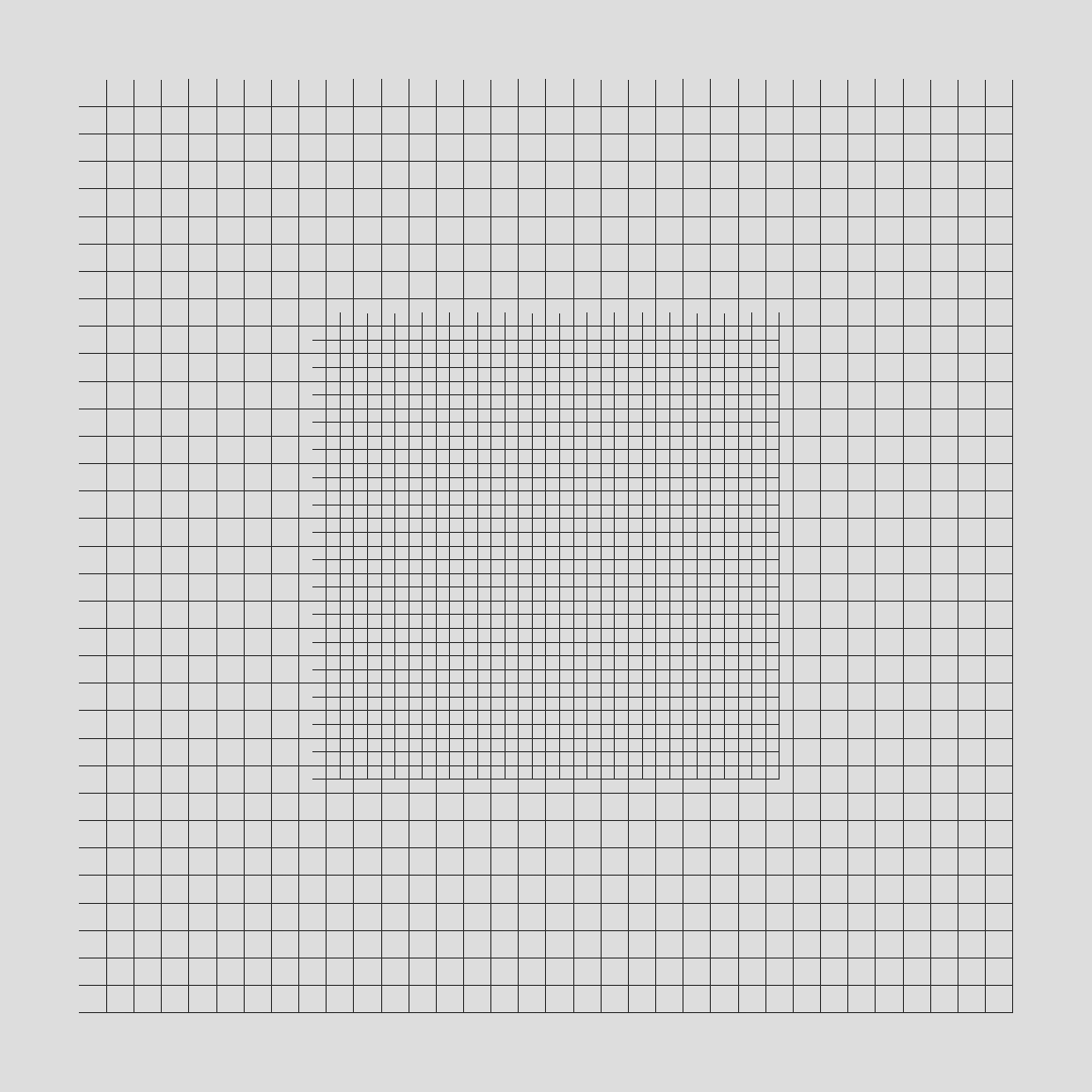
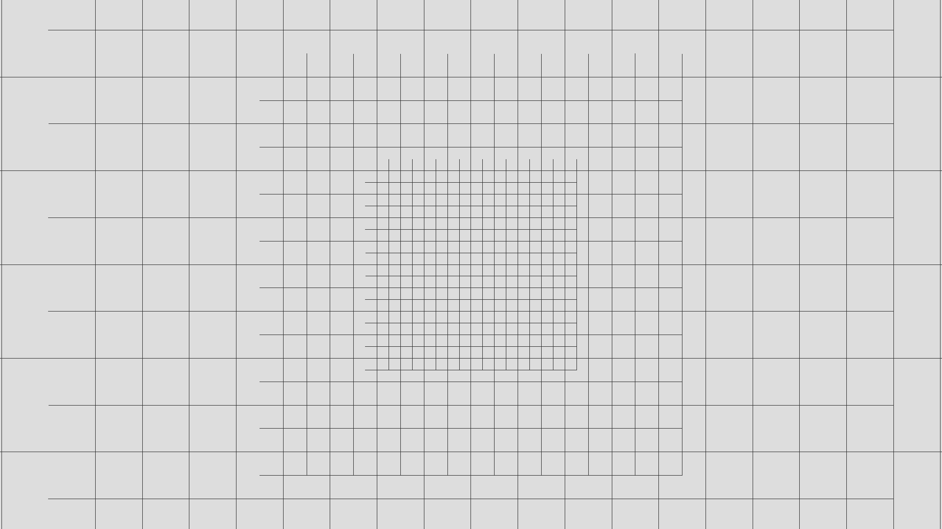
Here, it remains a problem: the overlapping of levels. To fix it, we dig a hole in grids around the first level. We now have an initial grid surrounded by square rings.
Deal with movements
It’s great, we have several grids, but it is not really enough for our needs. The main aim is to have something that adapts to the camera position. Naively, we could follow the projected point P’ with our different levels of detail, and it would works!
Yet, with this movement, we retrieve the same problem as the projected grid: vertices slide in the world space.
One solution is to discretize the space. Instead of moving levels of detail exactly as the camera, we try to fix the possible positions. In an optimal manner, we discretize the space for a given level the same way its grid is discretized. Thus, we can avoid the sliding effect while maintaining a grid adapted to the camera position.
At this point, levels are adapted to the xz coordinates of the camera, but not to its height. The first naive approach is to scale levels proportionally to the camera height. Once again, it will work, but it remains the same problem: vertices slide in the world space.
The final approach used here is to scale proportionally to the integral part of the log2(camera height). This way, we discretize once more the space to fix the problem.
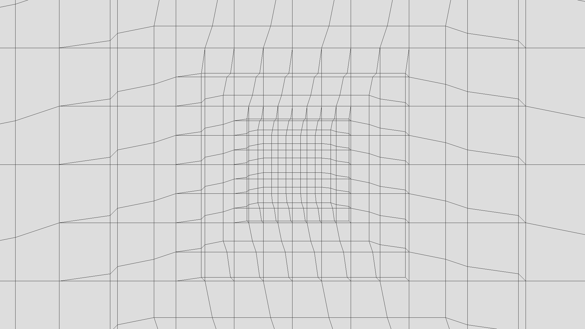
Morphing
At this stage, we have a working system. However, there remains one last problem. As the space is discretized, we can observe some “vertices popping” between levels, when moving the camera. An other problem is that the edges of the levels do not perfectly stick. This can lead to holes at the stitching.
To remove holes and smoothly change level of detail, we add a morphing on vertices. The aim is here to adapt slowly to the upper level.
There are two kinds of morphing:
- a morphing with the upper level
- a morphing following the camera height
For each vertex, we compute a morphing factor. If the factor is equal to 0, there is not displacement. If the factor is equal to 1, the vertex position is set to the parent level. The vertex can slide between these positions depending on the morph factor. As this sliding is only between two coordinates and not in the entire space, it does not really affect the rendering by adding swings.
Implementation
GitHub repository of this implementation.
Look at Florian Bösch - LOD with concentric rings implementation for an other implementation.
Initialization
Even if we want to use N levels of detail, we only need to generate two geometries: the initial grid and the ring around.
With the Three.js library, we can use a THREE.BufferGeometry in order to only generate what we need (only vertices in indices).
Here, we have a grid resolution K. To represent K * K squares, we need to store (K+1)^2 vertices. However, we also want an overlapping to be sure there is no holes between levels. So, we need to store (K+3)^2 vertices positions (xyz) to represent (K+2)^2 squares. Each square has two triangles, so there are 2 * (K+2)^2 triangles in the grid.
var geometry = new THREE.BufferGeometry();

// Storage of (K+2)^2 squares
var nbPoints = ( resolution + 3 ) * ( resolution + 3 );
var nbTriangles = ( resolution + 2 ) * ( resolution + 2 ) * 2 ;

// Allocate arrays
var positions = new Float32Array( nbPoints * 3 );
var indices = new ( ( positions.length / 3 ) > 65535 ? Uint32Array : Uint16Array )( nbTriangles * 3 );
geometry.addAttribute( 'index', new THREE.BufferAttribute( indices, 1 ) );
geometry.addAttribute( 'position', new THREE.BufferAttribute( positions, 3 ) );
After the buffer allocation, we can generate the grid with or without hole.
Adding to the scene
The simplest way to ensure all levels move together and simplify the addition or deletion of the plane is to put all levels inside a group.
// Simplified levels generation
var group = new THREE.Object3D();
for ( var i = 0; i < lodLevels; ++i ) {

  var geometry = ( i === 0 ? gridGeometry : gridOutsideGeometry );
  group.add( generateLODMesh( geometry, material ) );

}
We have the same problem as projected grid, that is to say the mesh need to be seen everywhere in the scene or the vertex shader will not be applied. To fix it, we only need to put the group on the camera.
camera.add( group );
Actually, my implementation is embedded in an object inheriting from THREE.Object3D. This way, we can directly add this object on the camera.
Vertex shader
Uniforms
The entire logic is defined in the vertex shader.
At this point, we have small grids with different geometries. With these pieces, we want to display something: here a plane (it could be a sphere for planet rendering as example)
To define a plane, there are several ways. Here, we will not choose the way with the fewer parameters, but a good balance between the number of parameters and computing time:
- the direction vector
- the up vector
- a point on the plane
We want to propose to select if we want to use default values (up vector = y, direction vector = z, point = origin) or use parameters values.
Moreover, we have some parameters to define the level of detail
- the grid resolution
- the current scale of the grid
- the current level
We already have some uniforms:
uniform float u_scale;
uniform int u_resolution;
uniform int u_level;
uniform vec3 u_planeUp;
uniform vec3 u_planeAt;
uniform vec3 u_planePoint;
uniform bool u_usePlaneParameters;
Prepare data
The first step in the main of the vertex shader is to prepare data. I mean that we ensure consistency of values and prepare data that will be used as the camera position.
The camera position can be easily extracted from the viewMatrix, without the need to set a uniform.
// Extract the 3x3 rotation matrix and the translation vector from the 4x4 view matrix, then compute the camera position
// Xc = R * Xw + t
// c = - R.t() * t <=> c = - t.t() * R
vec3 cameraPosition = - viewMatrix[3].xyz * mat3( viewMatrix );
If we want to use plane parameters, we need to compute the rotation matrix the camera projection on the plane and the origin projection on the plane.
// Compute the plane rotation (if needed)
mat3 planeRotation;
if( u_usePlaneParameters ) {
  vec3 planeZ = normalize( u_planeAt );
  vec3 planeX = normalize( cross( planeY, planeZ ) );
  planeZ = normalize( cross( planeY, planeX ) );
  planeRotation = mat3( planeX, planeY, planeZ );
}

// Project the camera position and the scene origin on the grid using plane parameters
vec3 projectedCamera = vec3( cameraPosition.x, 0.0, cameraPosition.z );
vec3 projectedOrigin = vec3( 0 );
if( u_usePlaneParameters ) {
  projectedCamera = cameraPosition - dot( cameraPosition - u_planePoint, planeY ) * planeY;
  projectedOrigin = - dot( - u_planePoint, planeY ) * planeY;
}
Space discretization
We want to discretize the space. This means a vertex can only be on some positions. To simplify the process, we work on a system coordinates between -0.5 and 0.5. We will scale the grid later.
The current level of detail depends on the scale retrieved with the uniform, but also depends on the height of the camera. The height is computed as the length between the camera position and its projection on the plane.
We compute the offset of the camera projection in order to center the grid on it. To discretize the space, we truncate the grid center with an accuracy of the size of a square.
// Discretise the space and made the grid following the camera
float cameraHeightLog = log2( length( cameraPosition - projectedCamera ) );
float scale = u_scale * pow( 2.0, floor( cameraHeightLog ) ) * 0.005;
vec3 cameraScaledPosition = projectedCamera / scale;
if( u_usePlaneParameters ) {
  cameraScaledPosition = cameraScaledPosition * planeRotation;
}
vec2 gridPosition = position.xz + floor( cameraScaledPosition.xz * float( u_resolution ) + 0.5 ) / float( u_resolution );
Morphing
As we have seen, there are two kinds of morphing:
- a morphing with the upper level
- a morphing following the camera height
The morphing with the upper level is really simple. It is basically the fractional part of the log2 of the camera distance to the plane.
// Compute the height morphing factor
float heightMorphFactor = cameraHeightLog - floor( cameraHeightLog );
It gets more complicated for the upper level morphing. Indeed, we move a vertex to come near the vertex of the upper level. If we do that, the lower level could also need to take care of this movement. This depends on the selecting morphing function.
To adapt to morphing levels to take care, we can use a uniform value.
uniform int u_morphingLevels;
In this implementation, I chose a linear morphing function. This way, we could need to know the grand parent morphing and not only the parent morphing.
// Compute morphing factors from LOD ancestors
vec2 morphing = vec2( 0 );
for( int i = 1; i <= 2; ++i ) { // 2 is the max allowed number of iterations
  if( i <= u_morphingLevels ) {
    morphing += computeAncestorMorphing( i, gridPosition, heightMorphFactor, cameraScaledPosition, resolution, morphing );
  }
}

// Apply final morphing
gridPosition = gridPosition + morphing;
The real morphing implementation is embedded inside a function, computeAncestorMorphing. There are several parts inside this function:
- a first check in order to know if we want to apply a morphing on this vertex. There are only three vertices on four that needs to move (one on two vertically, one on two horizontally).
- a morphing factor computing.
- a composition between morphing factors depending on the vertex position and the current level of detail.
vec2 computeAncestorMorphing(int level, vec2 gridPosition, float heightMorphFactor, vec3 cameraScaledPosition, float resolution, vec2 previousMorphing )
{
 // Check if it is needed to apply the morphing (on 1 square on 2)
 vec2 fractionnalPart = gridPosition * resolution * 0.5;
 if( level > 1 ) {'
   fractionnalPart = ( fractionnalPart + 0.5 ) / pow( 2.0, float( level - 1 ) );
 }
 fractionnalPart -= floor( fractionnalPart );

 // Compute morphing factors (based on the height and the parent LOD
 vec2 squareOffset = abs( cameraScaledPosition.xz - ( gridPosition + previousMorphing ) ) / float( level );
 vec2 comparePos = max( vec2( 0.0 ), squareOffset * 4.0 - 1.0 );
 float parentMorphFactor = min( 1.0, max( comparePos.x, comparePos.y ) );

 // Compute the composition of morphing factors
 vec2 morphFactor = vec2( 0.0 );
 if( fractionnalPart.x + fractionnalPart.y > 0.49 ) {
   float morphing = parentMorphFactor;
   // If first LOD, apply the height morphing factor everywhere
   if( u_level + level == 1 ) {
     morphing = max( heightMorphFactor, morphing );
   }
   morphFactor += morphing * floor( fractionnalPart * 2.0 );
 }
 return float( level ) * morphFactor / resolution;
}
Back to the world space
The last step in the main is to back to the world space. We only need to scale the position and use the plane parameters (if needed).
// Compute world coordinates (if needed)
vec3 worldPosition = vec3( gridPosition.x * scale, 0, gridPosition.y * scale );
if( u_usePlaneParameters ) {
  worldPosition = planeRotation * worldPosition + projectedOrigin;
}

// Return the final position
return vec4( worldPosition, 1.0 );
Usage
Shader using LOD, projected grid or simple grid source code
Great! We set up a LOD system. But how to really use it?
A simple way is to partition the shader inside smaller pieces that can be part of another shader.
The three.js way is the following :
THREE.ShaderChunk["lod_pars_vertex"] = [
  ... // Define here computePosition() and uniforms
].join('\n');


THREE.ShaderChunk["lod_vertex"] = [
  'worldPosition = computePosition( worldPosition );',
].join('\n');
The ‘lod_pars_vertex’ need to be added outside the main whereas the ‘lod_vertex’ need to be added inside the main.
To demonstrate the ability to use multiple representation system for the same rendering, I use a function that created the final vertex shader.
THREE.ShaderLib['example_main'] = {
  uniforms: {

    'u_animate':  { type: 'i', value: true },
    'u_time':     { type: 'f', value: 0.0 },

  },

  buildVertexShader: function( shaderChunk ) { return [

    'varying vec3 vWorldPosition;',

    'uniform bool u_animate;',
    'uniform float u_time;',

    'const float amplitude = 50.0;',
    'const float wavelength = 4.0;',
    'const float speed = 1.0;',

    THREE.ShaderChunk[ shaderChunk + "_pars_vertex" ],

    'float getHeight( vec2 inDir, vec3 position ) {',
    ' float height = sin( position.x * inDir.x + u_time * speed ) * 0.8 + cos( position.z * inDir.y + u_time * speed ) * 0.2 ;',
    ' return height * height * height + 0.5 ;',
    '}',

    'void main (void) {',

      'vec4 worldPosition = vec4( position, 1.0 );',

      THREE.ShaderChunk[ shaderChunk + "_vertex" ],

      'if( u_animate ) {;',
        'vec3 heightPosition = worldPosition.xyz / wavelength;',

        'float height = getHeight( vec2( 0.3565, 0.265 ), heightPosition ) * 0.3 +',
        '               getHeight( vec2( 0.07565, 0.0865 ), heightPosition ) * 0.6 +',
        '               getHeight( vec2( 0.8, 0.99 ), heightPosition ) * 0.1;',
        'worldPosition.y += height * amplitude - amplitude * 0.5;',
      '}',

      'vWorldPosition = worldPosition.xyz;',
      'gl_Position = projectionMatrix * viewMatrix * worldPosition;',
    '}'
  ].join('\n'); },

  fragmentShader: [
    'uniform bool u_animate;',

    'const float amplitude = 50.0;',

    'varying vec3 vWorldPosition;',

    'void main (void) {',
      'if( u_animate ) {',
      ' float value = ( ( vWorldPosition.y + amplitude * 0.5 ) / amplitude ) - 0.5;',
      ' gl_FragColor = vec4( vec3( 0.5, 0.5, 0.5 ) + value * 0.2, 1.0 );',

      ' float textureSize = 50.0;',
      ' if( mod( vWorldPosition.x, textureSize ) > textureSize * 0.5 ) gl_FragColor += vec4( 0.2, 0, 0, 0 );',
      ' if( mod( vWorldPosition.z, textureSize ) > textureSize * 0.5 ) gl_FragColor -= vec4( 0.2, 0, 0, 0 );',

      ' textureSize *= 20.0;',
      ' if( mod( vWorldPosition.x, textureSize ) > textureSize * 0.5 ) gl_FragColor += vec4( 0, 0.2, 0, 0 );',
      ' if( mod( vWorldPosition.z, textureSize ) > textureSize * 0.5 ) gl_FragColor -= vec4( 0, 0.2, 0, 0 );',

      ' textureSize *= 20.0;',
      ' if( mod( vWorldPosition.x, textureSize ) > textureSize * 0.5 ) gl_FragColor += vec4( 0, 0, 0.2, 0 );',
      ' if( mod( vWorldPosition.z, textureSize ) > textureSize * 0.5 ) gl_FragColor -= vec4( 0, 0, 0.2, 0 );',

      '}',
      'else {',
      ' gl_FragColor = vec4( 0.2, 0.2, 0.2, 1.0 );',
      '}',
    '}'
  ].join('\n')
};
Final usage:
var shader = THREE.ShaderLib['example_main'];
var uniforms = THREE.UniformsUtils.clone( shader.uniforms );
// Set others uniforms ...

this.material = new THREE.ShaderMaterial( {
  uniforms: uniforms,
  vertexShader: shader.buildVertexShader( 'lod' ),
  fragmentShader: shader.fragmentShader
} );
Resources
External resources:
Resources around this implementation: